

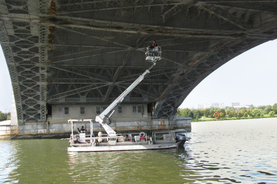
A historic bridge spanning the Potomac River between the Lincoln Memorial in Washington, DC and Arlington National Cemetery in Arlington, VA, Arlington Memorial Bridge was constructed in 1931 with 10 concrete open deck spandrel arch approaches and one steel-trussed double-leaf bascule span. Traversed by more than 60,000 vehicles per day, the Arlington Memorial Bridge is both a key connector in the DC metro area and retains a place of honor on the National Register of Historic Places. The 2,128’ bridge carries six lanes of traffic into and out of the District, with 14’ wide sidewalks on each side. The bascule span is now fixed in place, having last opened for maritime traffic in 1961.
Over recent years, the Clark Nexsen bridge inspection team has performed multiple inspections of the Arlington Memorial Bridge, including six in-depth inspections, two routine inspections, and one special inspection – all with accompanying load ratings.
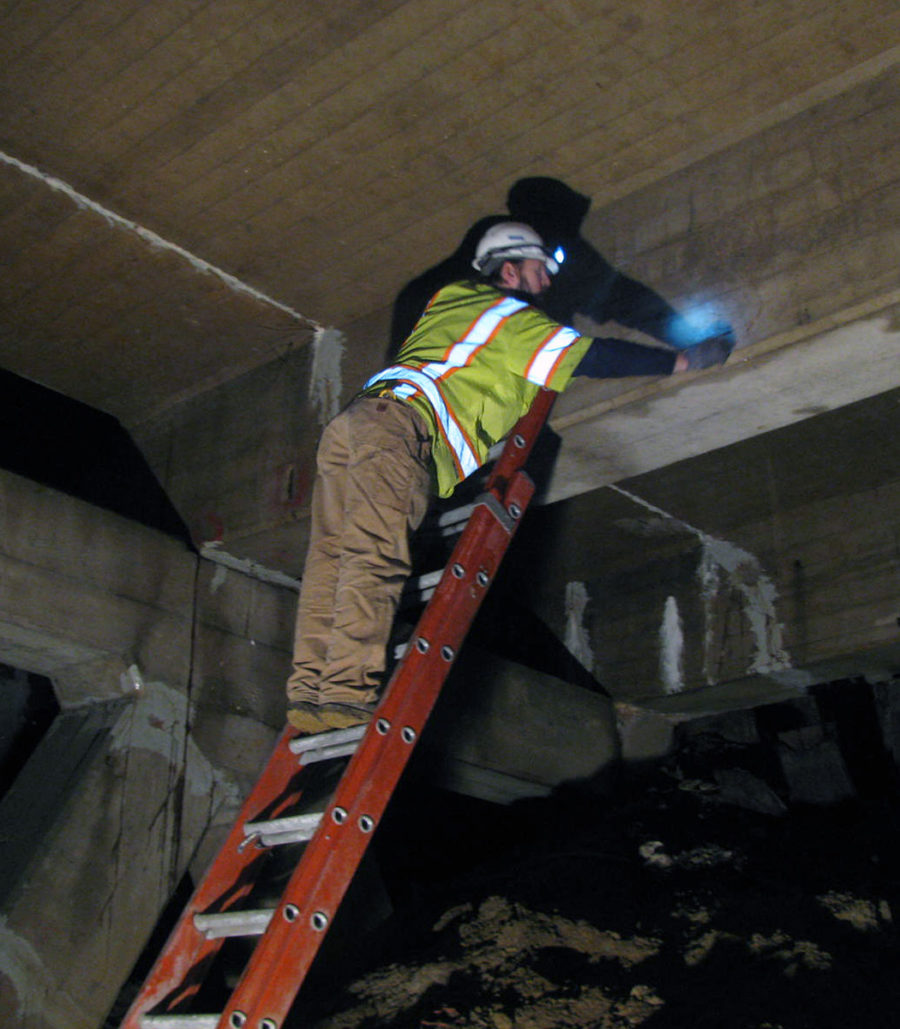
In-Depth Inspection. Working with the Eastern Federal Lands Highway Division of the Federal Highway Administration, Clark Nexsen bridge inspectors have performed in-depth inspections on both the steel double-leaf bascule span as well as the concrete arch approach spans of Arlington Memorial Bridge. Initially, our routine inspections identified widespread deterioration on the structure, helping bring to light the need for more detailed condition assessments and structural evaluation. Requiring meticulous attention to detail, the in-depth inspections involve bridge engineers combing over the structure and compiling detailed notes on the condition of the bridge. The bascule span is composed primarily of steel, requiring particular attention as it has been subjected to some form of water exposure for more than 80 years, resulting in developed areas of corrosion. For locations with significant corrosion, areas are thoroughly cleaned and wasted steel is removed. Deterioration lengths are established into defined ranges along affected members and precise ultrasonic measurements are taken to determine the thickness of steel that remains at distinct locations within each range. The comprehensive, 2,000 page inspection report illustrated our inspection findings via technical writing and photographs, and also via highly-detailed cross section schematics of each member in its deteriorated condition. Both emergency repair and programmed rehabilitation plans have been generated as a result of our in-depth inspection efforts. The overall scope of the latest inspection is the largest single inspection effort the EFLHD has ever commissioned.
Load Rating. The load rating was attached as an appendix to the inspection report, but individually comprises more than 1,000 pages of Load Factor Rating Analysis of the bridge. Clark Nexsen engineers load rated this immensely complex structure using an array of tools. The primary mode of analysis was through custom spreadsheets based on influence line loading of the structure using various vehicles (HS20, TYPE 3, SHV’s) and derivation of distribution factors to identify the critical loads acting on the structure. Several spreadsheets were needed due to the range of structural components the bridge features, such as open spandrel arches with concrete floorbeams in the arches and over the piers, and bascule leaves with both single beam and trussed main girders, floorbeams, and stringers. The bascule span has varying configurations within the limits of the fixed bascule pits and the actual bascule leaves. Additionally, the bridge features massive trunnion posts due to its originally movable configuration; these trussed posts still support the superstructure and so had to be analyzed. To provide accurate input for the spreadsheets, portions of the structure were first modeled in STAAD to obtain loads as needed. In addition to the custom spreadsheets, AASHTOWare Bridge Rating software was used where possible; particularly in the stringers where the software was most suited to the structural configuration. Another significant component of the load rating was to determine the capacities of the sometimes heavily deteriorated members having up to 75 percent loss of section to steel members and concrete members with large spalled areas with exposed reinforcing. To achieve this, the in-depth findings were carefully entered to accurately model the deteriorated capacities. This effort was a major contributor to identifying areas that needed urgent retrofitting. In subsequent ratings, where members had been retrofitted, the capacities were revised to include the retrofits; thereby verifying the repairs were performing as intended.
