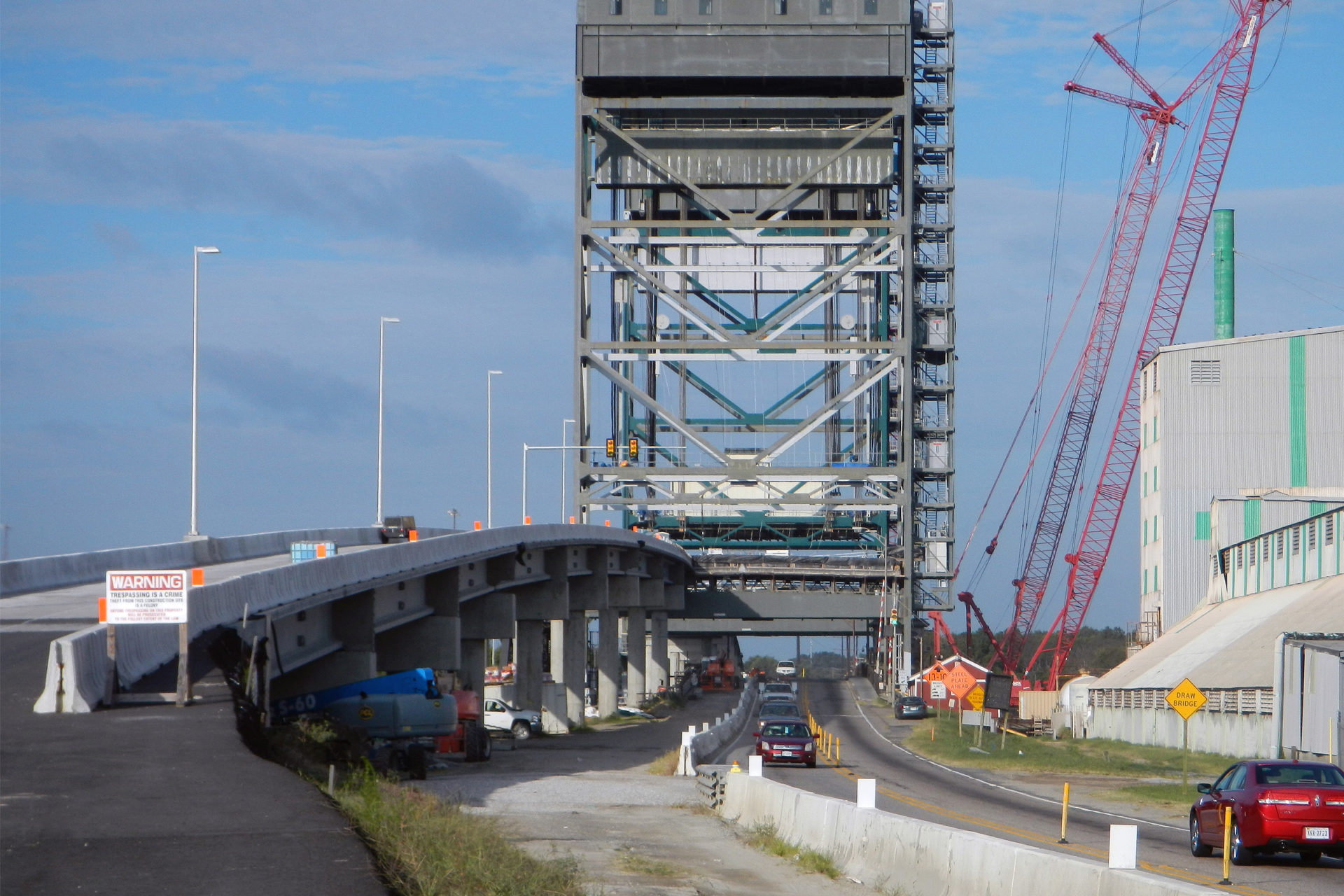
A complex project phased over multiple years, the Gilmerton Bridge Replacement constructed a movable bridge with a vertical lift span directly over an existing movable double leaf bascule bridge and directly adjacent to a movable single leaf bascule railroad bridge. Throughout this phased construction process, the contractor worked with Clark Nexsen’s bridge team to assist with various needs ranging from fender redesign and drilled shaft analysis to construction vehicle placement on both the new and existing approach spans. Highlights from our work include:
Sheet Pile Design and Analysis. Clark Nexsen’s bridge team reviewed boring logs and soil conditions for applicability to specified sheet piling locations, using the findings to perform several sheet pile designs. The designs included all typical members including struts, wales, sheets, and piles, and all cutting and filling requirements were incorporated into the design. The design also considered iterative placement of the sheet pile components; initially with the driving template not placed, later with the template, and finally with traffic and superimposed load on the retained fill. Where necessary, piles were designed as cantilevers and checked for major and minor axis bending. The majority of the analyses were performed by hand with Pile Buck and ProSheet software used to provide overall loads and as a back-check.
Analysis of As-Built Abutment Piles. During installation, some eccentricity had been introduced to the abutment pile locations and there was some concern that the capacity had been compromised. Our bridge engineers reviewed the as-built condition of the piles and recomputed all capacities with the in-situ soil conditions and the revised center of gravity of the pile group. The analysis included consideration for the exacerbated lever arm distance of the backwall and approach slabs. Further, the rigidly connected portion of the wingwall supported on the abutment footing had potential to exert earth pressure on one of the piles; however, due to the large moment of inertia of the pile group overall, the net result did not significantly decrease the pile capacity.
Review of Falsework Calculations. With the contractor’s junior engineers having performed all necessary calculations but unable to stamp their design, Clark Nexsen’s bridge team was tasked to complete an independent design and provide sealed documents. To accelerate the process for the contractor and utilize the existing materials, our engineers opted instead to review the existing calculations and provided markups back to the contractor’s engineer. These revised calculations were resubmitted to us, upon which we were able to stamp the drawings and provide the contractor with the necessary documents. This process saved significant time and also aided in the development of the junior engineer’s capabilities.
Construction Loading Analysis. During the construction sequence, several extremely heavy loads were placed on both the existing structure and the newly built structure, including elements such as concrete pump trucks, cranes, and several trucks loaded with massive sections of steel columns for the vertical lift span towers. The heaviest of these resulted in a gross vehicle weight of 156,000 lbs. Our bridge engineers were able to ensure the loading was within tolerance for the bridge capacity, despite a complex analysis due to the existing structure’s locations of severe loss of section to the girders.
Fender System Redesign. The fender system initially designed for the new structure required the existing bascule pit, tremie seal, and timber piles to be completely removed from below the waterline, deep into the subsurface. Unfortunately, it became increasingly evident that this solution would not be economically feasible, and the contractor worked with Clark Nexsen to assist in the redesign of the new fender system. Our bridge team was able to contribute to a ship impact analysis that drove the redesign. The new design was fully fleshed out by our engineers, culminating in the submittal of shop drawings detailing all rebar requirements.
